SCT013-000-100 clamp and ATTINY45 microcontroller

How do you install a power usage monitor? Without mayor changes to your distribution panel? 
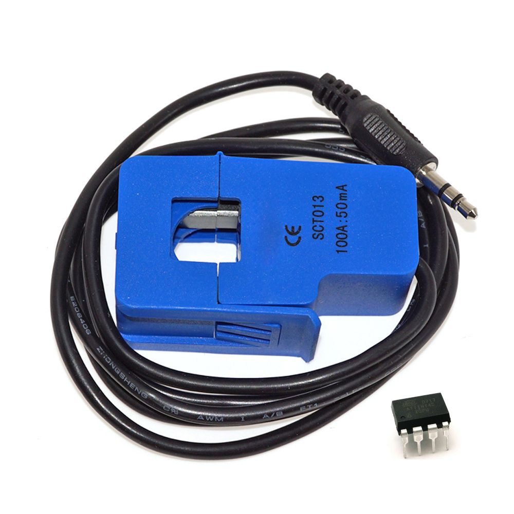
Well, simply clamp a split-coil current transformer like the SCT013-000 in the picture onto the electric cable to be measured.

So far so good. The current transformer generates a current in the secondary coil that is proportional to the current going through the primary coil which is proportional to the apparent power usage, assuming a resistive load.

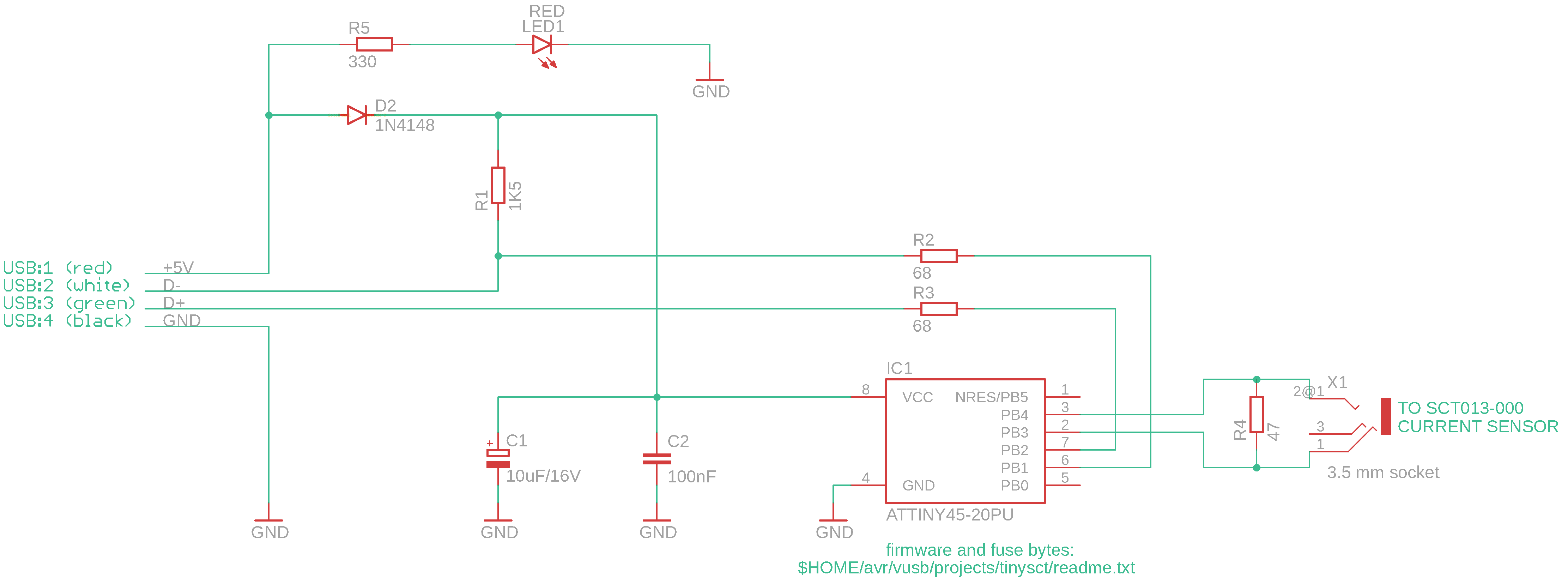
The challenge is to measure the current and make it available through USB. The first step is to convert the current to a voltage by connecting a load resistor to the secondary coil. Unfortunately the result is an AC voltage, which is more difficult to measure than DC.

The trick is to determine the average voltage by taking many samples and calculate the mean value. The average value of a sine wave is zero. But the average of the absolute values is proportional to the RMS value.

The bipolar differential ADC of the ATtiny45 microcontroller can handle this without additional hardware. And connecting the microcontroller to a USB interface is very simple too thanks to the V-USB project. Only three resistors and a decoupling capacitor are needed.

The rest is done in firmware. Not even an external crystal or resonator is needed as the internal RC oscillator is used. It is calibrated by the firmware at power up.


USB Power Meter circuit

SCT013-000-100 mounted

The firmware samples during approx. 200 ms, i.e. 10 waves @ 50 Hz. The sum of the samples is divided by the number of samples (approx. 1600) to achieve the average voltage. The average voltage is proportional to the RMS voltage which is proportional to the current and therefore to the power usage.

On the host a command line tool called tinysct retrieves the result from the microcontroller through USB.

All documentation (e.g. how to calculate the load resistor), firmware, command line tool and schematics are available on github. Enjoy!